
- Hainan Jinpan Smart Technology Co., Ltd.
- Основные продукты: Трансформатор с заливом смолой, Трансформатор с вакуумной пропиткой изоляции, Выключатель для открытых подстанций, Средненапряжные комплектные блок-подстанции
Главная > Новости компании > Harmonic Mitigating Transformer

-
 Song
Добро пожаловать в мой магазин. Я рад вам обслуживать. Не стесняйтесь задавать мне любые вопросы.
Song
Добро пожаловать в мой магазин. Я рад вам обслуживать. Не стесняйтесь задавать мне любые вопросы.
Ваше сообщение превысило лимит.
Новости компании
The Harmonic Mitigating Transformer (0° or -30° primary-secondary Phase Shift)
Even if it is possible with a K-type transformer, depending on the quantity of Zero Sequence harmonics (triplets), to support these non-linear loads, how can one know which loads will be applied in 6 months, 1 year, or more?
Special secondary interconnections construction produces a cancellation of the 3rd, 9th, 15th harmonics (triplets). So, if we build a transformer with a Delta primary and a double interconnected winding secondary to cancel the triplen (zero sequence harmonics), we will have:
An adaptable transformer for non-linear loads
A low-impedance cancellation of the 3rd, 9th, 15th harmonics
A better equilibrium of phases and less harmonic voltage distortion (low-impedance Zero Sequence).
An electrostatic screen and a peak cut-off filter could also be installed for additional protection against common mode noise.
The installation of this kind of transformer is the same as for an ordinary transformer. Many existing applications use this type of construction.
Because of its Phase Shifting of 0°, it should be noted that by placing this type of transformer in a system composed of already existent Delta-Wye transformers (-30º), a cancellation of the 5th and 7th harmonics will be obtained. The 5th and 7th harmonics from the transformers will try to cancel the 5th and 7th harmonics coming from the already existent Delta-Wye transformers (-30º). This will also improve the power factor.
(ex.: -15°, -45º; or 0º, -30° between the secondary double windings dual output)
This is a transformer with three phases on the primary and six on the secondary, so two sets of three phase outputs on the secondary. Because of the phase shifting between the two sets of three phase outputs:
A cancellation of the 3rd, 5th, 7th, 9th, 15th, 17th and other harmonics like the 19th on the secondary with a 0º and –30º angle difference and low impedance.
An improvement in the equilibrium of the phases.
A cancellation of triplets with only a difference of 0º and –60º.
A cancellation of the 5th, 7th, 17th and 19th harmonics with an angle difference of -15º and -45º, and the triplets are trapped in the Delta winding.
An important power factor improvement (see description of the power factor in Electrical Problems Related to Power Quality).
Typical and General Construction for a Transformer in a Demanding Environment with Non-linear Loads
Coil connections should be Delta on the primary and Wye on the secondary. Even better, use double windings on the secondary which would diminish harmonic voltage distortions caused by current distortions (V=IR); this type of winding cancels triplets (3rd, 9th on the secondary) at very low impedance. To obtain the best resistance to thermal and physical shock, coils should be made from copper, not aluminum. In order to have the same wire resistance between aluminum and copper, it would take 1.6 times the surface of aluminum wire as compared to that of copper.
The K-factor value should be well established with respect to the anticipated loads; for example, K13 can take up to 33% of the fundamental in the 3rd harmonic, 20% in the 5th, 14% in the 7th, and 11% in the 9th.
A high performance grounded electrostatic shield may also need to be installed. As well, peak cut-off circuits and hybrid filters can be installed to make the transformer more efficient in protecting the loads in question.
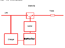
Stand By Power Supply SystemsThese systems provide an electric current source when outages occur. As soon as an outage is detected, the transfer switch starts the AC converter. This transforms the current coming directly from the batteries into an alternating current capable of powering the computer for at least another 10 minutes.
These backup power supplies detect an outage in less than 4 microseconds, which is ample time to prevent interruptions. These units are very inexpensive, but they only offer minimal filtration and no galvanic isolation (neutral-ground), which means that there will be no cancellation of common mode (neutral-ground) voltage. The importance of the network will determine whether or not the savings made are worth it.
These units isolate line to load at all times and are installed between the line and the load. They constantly provide power to keep equipment working (computers, servers, terminals, PLCs, etc.). In a blackout situation, they output a perfect sine wave without any transfer time or interruption. There are four types of UPSs.
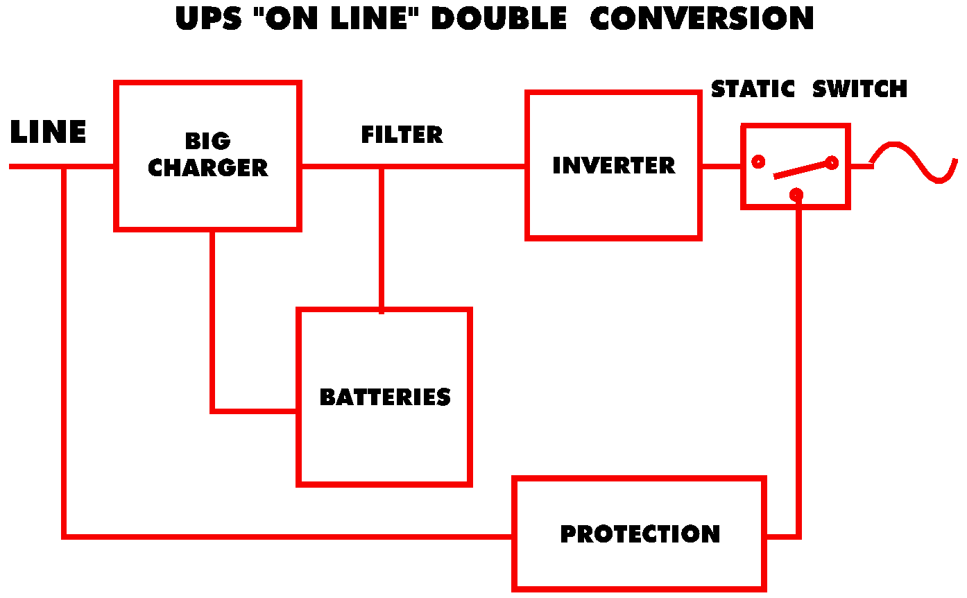
The "On Line" Double Conversion UPS
An internal rectifier transforms AC current into DC current. The DC current charges the batteries so they are always ready to be used, and a converter transforms the DC battery current into AC current to power the computer. These sources output clean power and guarantee protection against all forms of electrical problems. Special attention must be given to static switches which usually require a specialized transformer for protection. It should be noted that the battery charger can be a harmonic source that will have to be corrected with filters or by phase shifting.
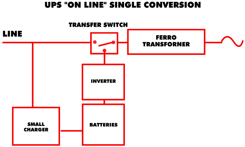
An internal rectifier transforms AC current into DC current. This current charges the batteries while the line powers a ferroresonant transformer which isolates, powers, filters, and corrects the load voltage. It is always ready for use when a blackout or power anomaly occurs. When an outage occurs, a converter transforms battery DC current into AC current to power the load. While this is happening, the ferroresonant transformer's capacitors support the load by saturating the transformer's core. These sources always output clean current and guarantee protection against all forms of electrical problems. This type of product is very well adapted for demanding applications because of its robustness and redundancy.
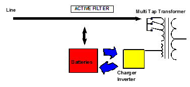
This technology is relatively new. The current is fed to a special isolation transformer which uses the multi-tap method to control its own voltage. A contact is established with a dual-purpose converter (charger and converter) which charges the batteries or helps to stabilize the line. In a blackout situation there is no transfer; the converter uses the batteries to power itself and transforms DC battery current into AC current to power the application.
Normally, a DC motor powered by a rectifier connected to the voltage of the local supply circuit makes a generator turn. This powers the load with an electrical source that is independent of the local supply circuit. When an outage occurs, the initial supply keeps the generator functioning or a battery keeps the DC motor working until the diesel backup generator starts. The diesel motor then takes over for the DC motor for the length of the outage.
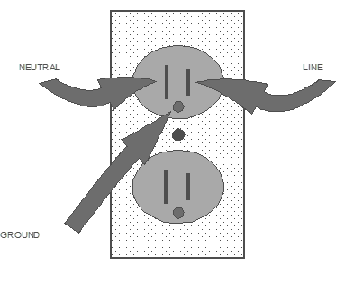
The Installation of Dedicated Outlets for Computerized EquipmentIt is very important to check the electrical outlet before plugging in a computer. Indeed, this often constitutes the most neglected point of the system. No voltage should exist between the neutral and the ground.
The neutral wire is connected to the ground and to the secondary of the transformer, with the exception of the voltage provoked by the return current. This is caused by the phase unbalances on a three-phase, four wire system or the current of a simple phase system (V=IR , very little common mode voltage (neutral to Ground) which should be seen at the receptacle
However, because of harmonic currents, what should have been cancelled in a linear three-phase system is not, and a voltage is found between neutral and ground. In addition, to complicate things even more, the presence of this common mode voltage is an indication of voltage surges due to the commutation of the equipment.
It should be noted that the higher the frequency, the more the wire's resistance increases because the current flows on the exterior surface of the wire. Therefore, the wire acts as though it has a smaller diameter. The impedance corresponds to the wire's resistance, which is proportional to the frequency. The longer the wire, the greater the voltage between the neutral and the ground which will therefore cause problems to the electrical circuit.
Indeed, a high frequency current will heat up the circuits and damage the computers. This situation will be caused by the computerized signals' reference to ground and the standard computer protection (internal filter, internal peak cut-off circuit).
The Ideal ApproachIt is essential to plan the installation of outlets for computers, laser printers, and photocopiers in collaboration with computer executives. Depending on the needs, you could then proceed to the installation of dedicated orange, gray, blue (with SPD) and white outlets.
| Type of Receptacles 15A –120V | ||
| Color | Type | Application |
| White or Black | Ordinary | Standard |
| Grey | Ordinary | Printer-Copier |
| Blue | With Protection | Sensitive |
| Orange | Dedicated Ground | Computer |
A dedicated outlet should signify a less loaded neutral and therefore a less important neutral-ground voltage difference, which has the advantage of prolonging the useful lifetime of computerized systems. But there's more. Most electronic equipment is protected by filters and peak cut-off circuits. Voltage spikes and high frequency noise can be found on the ground. If the equipment is connected to a dedicated circuit, this noise or these voltage spikes will be directed to the panel. In the opposite case, the spikes and noise would find a path through the communication cables of another computer (ground of the signal) and would provoke a ground loop.
Linear loads (heating, incandescent lighting, etc.) do not go well with non-linear loads (computers, laser printers, and photocopiers). In the non-linear family, computers, do not get along well with the electrical properties of laser printers and photocopiers which consume a great amount of current in an abrupt and irregular fashion, affecting the voltage. The voltage fluctuations that they provoke can seriously damage a computer or can even simulate a blackout.
For an adequate installation, we will use the white outlets for traditional linear loads. Then we will reserve dedicated orange outlets for computers and gray outlets for photocopiers and laser printers.
Each outlet will have its own dedicated circuit on a circuit breaker. If you should place many outlets on one circuit, they should be in the same box. They will also have a live wire (black), a neutral (white), and an isolated ground wire. In addition, a naked ground wire allows continuity of grounds and the box.
We will make sure to balance the gray outlets (printers and photocopiers) in the panel, as well as the orange ones (computers) on three phases. Next, the three phases would have to be brought as close as possible to where they will be used in order to minimize magnetic fields (one phase often cancels out another).
Take note that big photocopiers must have their own circuit because their energy demands are large, abrupt and irregular.
Blue outlets with SPD often constitute a problem, particularly if their ground is shared with an orange or ordinary (black) outlet, and if other computers are connected to it. This type of outlet's internal peak cut-off circuit will direct these voltage spikes to the ground. The voltage spike could also find a shorter path (low impedance) through the communication cable of the computer, which is plugged into the orange outlet. To avoid this kind of situation, a blue outlet should have its own circuit (an outlet = a circuit breaker).
Panel PlacementA panel will be dedicated to linear loads and another to non-linear loads. The one dedicated to the non-linear loads will be three-phase and situated as close as possible to the computers in order to minimize the possibilities of voltage distortion. Indeed, with non-linear loads, we find current distortions and, according to Ohm's law (V=IR), impedance amplifies the current distortion to produce a voltage distortion.
A transformer placed as close as possible to this panel will power the isolated ground panel for non-linear loads. Remember that distance plays an important role.
The transformer's neutral will also have to be connected to the ground. On the panel, there should be a wire for the isolated ground connected to an isolated terminal on the panel and another wire on the box itself for the security ground. It is recommended that a flat metallic strip be connected between the isolated terminal and the equipment ground (mechanic); this will improve the equality of the potential of grounds and also could help for dissipation of spikes (33kHz typical).
In addition, the transformer will be composed of a delta winding on the primary and a Wye winding on the secondary. It will be a K-type transformer equipped with a peak cut-off circuit. Better still, for important installations, it is recommended to use a transformer with a delta primary and double windings (Harmonic Mitigating Transformer) on the secondary. This will give a better output due to the cancellation of the Zero Sequence harmonics which will appear at very low impedance on the secondary (see Ohm's law). It will also be important to install peak cut-off circuits (SPD), be it on the transformer or in the distribution panel, because these hybrid filters (SPD) will still provide a minimal protection for a dedicated panel.
GLOSSARY OF TERMSCapacitance:
Capacitance is the property of a system of dielectrics and conductors that allows for the storage of electrical separated charges when a potential difference exists between the conductors
A capacitor does not dissipate real energy (Watts)
Converter:
A device which can be used to change alternating current power to direct current power or vice versa, or from one frequency to another
Faraday Shield:
A grounded metallic barrier than can be used for enhanced isolation between the windings of an isolation transformer
Filter, band pass:
A filter that has a single transmission band, neither of the “cut-off” frequencies being zero or infinite
Filter, band reject:
A filter that has a single attenuation band, neither of the “cut-off” frequencies being zero or infinite
Impedance:
Propensity of a circuit or device to impede the flow of current
The real part of impedance is the resistance, and the imaginary part is the reactance
Inductance:
Represents the propensity of a conductor to store energy in an associated magnetic field
Opposes the change of AC current but does not oppose the flow of DC
Can be thought as electrical inertia
Joule:
- Предыдущая страницаJST company
- Следующая страницаPeak Cut-Off Circuits (Surge Protective Device or SPD)
-
 G12V190PZL1 JDEC JICHAI JINAN дизельный двигатель марки CHIDONG запчасти воздушный фильтр 12VB.36M.40/50
-
Высокочастотный трансформатор для сварки термопластов и производства автомобильных внутренних деталей
-
Трансформатор тока шинного типа KCT-816 с раздвижным сердечником
-
Трансформатор тока разъемного сердечника шинной шины с выходом 5А для устройств контроля
-
KCT-816 2500:5A Шина-типа раздельно-кольцевые трансформаторы тока
-
RS1000-1500A/333mV Открыто-закрытый трехфазный гибкий rogowski-кованный токовый трансформатор
-
Гибкий токовый трансформатор на основе Rogowski-ой катушки для измерения высокочастотных переменных токовых сигналов
-
Дешевый
-
Трансформатор электроизоляционного типа
-
Цены завода-производителя. Цены на трехфазный понижающий трансформатор
-
Высокопроизводительный трехфазный промышленный сухой реактор с железным сердечником на переменный ток
-
Производитель
-
Популярные рекомендации. Трехфазный трансформатор. Сухой трансформатор
-
Профессиональная фабрика. Трехфазный трансформатор. Сухой трансформатор
-
Китайский завод. Эпоксидно-массовый сухой трансформатор высокого напряжения для распределительной сети
-
Трехфазный сухой трансформатор
-
Эпоксидная смола
-
Реактор высокого напряжения
Популярные поиски
- Электрический трансформатор
- Сервис распределения
- трансформатор тока
- Электрические трансформаторы
- Высокочастотный трансформатор
- Электрический трансформатор
- устройство для экономии энергии
- LED-трансформаторы
- повышающий преобразователь
- Преобразователь переменного тока
- Преобразователь частоты
- электронный трансформатор
- Светотрансформаторы
- Тороидальный трансформатор
- автотрансформатор
- трансформатор тока, индуктивность
Hainan Jinpan Smart Technology Co., Ltd.
