
- Hainan Jinpan Smart Technology Co., Ltd.
- Основные продукты: Трансформатор с заливом смолой, Трансформатор с вакуумной пропиткой изоляции, Выключатель для открытых подстанций, Средненапряжные комплектные блок-подстанции
Главная > Новости компании > Peak Cut-Off Circuits (Surge Protective Device or SPD)

-
 Song
Добро пожаловать в мой магазин. Я рад вам обслуживать. Не стесняйтесь задавать мне любые вопросы.
Song
Добро пожаловать в мой магазин. Я рад вам обслуживать. Не стесняйтесь задавать мне любые вопросы.
Ваше сообщение превысило лимит.
Новости компании

Peak Cut-Off Circuits
(Surge Protective Device or SPD)
These semi-conductors (MOV: metal oxide varistor) are barely conductive below a certain voltage, which become conductive above this voltage. On a 120-volt circuit, if we place this semi-conductor between the line and the ground, when a voltage spike occurs, the semi-conductor will become conductive and will discharge this extra voltage to the ground.
Semi-conductors have a finite life span, and after a certain number of shocks, they can become ineffective. They must be replaced often, each year in some cases, if their tolerance in joules and in maximum peak current becomes too low. Many systems do not allow easy testing of the MOVs.
Here are a few SPD characteristics to look for:
They can be equipped with a high frequency filter (10 kHz-100 MHz)
They must be easy to replace and come with warning lights in case of failure. In certain cases they should come equipped with an external alarm
Low-scale units can become inefficient within six months
Note: Even though they are often called filters or line conditioners, semi-conductors only filter the high frequencies (10 kHz-100 MHz) only if they are equipped with hybrid filters. They never isolate line applications. A transformer must be added to obtain this kind of protection.
Isolation transformers are sometimes equipped with peak cut-off circuits and filters and they can have a galvanic isolation. They therefore become great line conditioners protecting against noise and spikes.
Voltage Regulating TransformersAs well as insuring protection against spikes and surges, voltage regulators filter most of the electric noise which is often a hidden source of problems. Voltage regulators are more expensive than peak cut-off circuits (SPD), but they protect much better since most are equipped with an isolation transformer. There are three types of voltage regulators on the market: the ferro-resonant transformers, tap switching transformers and the electronic voltage regulator.
Isolated Delta-Wye TransformersThis type of transformer is very popular. They cost less and can also isolate the application from the line.
Peak cut-off circuits, filters and a double electrostatic shield can be added as options for protection against common mode noise and voltage spikes found on the line (for information on harmonics, see K-type, Delta-Wye for Non-linear Loads).
Because of the galvanic isolation, there will be a link on the secondary between the neutral and the ground which eliminates the possible voltage between the neutral and the ground on the secondary of the transformer.
To be more efficient, these transformers must, if possible, be installed close to the application.
Since standard transformers were built to support linear loads, they may overheat and become damaged with non-linear loads.
Declassification of a 4 wire Delta-Wye transformer according to CBEMA without K factor:
| PH A | PH B | PPH C | Average | |
| RMS AMPS | 310 A | 346 A | 337 A | 331 A |
| PEAK AMPS RMS | 705 A | 793 A | 729 A | 742 A |
So: 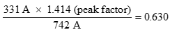
Then: The kVA of the transformer x 0.630 = usable kVA
K-type Delta-Wye for Non-linear LoadsK-type transformers (K4, K9, K13, K20) are isolation transformers. They become line conditioners if they are equipped with special electrostatic screens and peak cut-off hybrid filters on the secondary and the primary. K-type transformers are designed to support the supplementary losses due to the harmonic current circulating in the windings.
The number indicating the factor (K4, K9, K13,) is the multiplication factor of the losses due to the Foucault currents in the windings that this transformer can support, following the UL 15.61 standard.
K-Type SuggestionsHigh K-Ratings do have some disadvantages, namely larger size, lower efficiencies (especially at lower load factors) and lower impedance which causes potentially higher fault currents. As a result, it is not always desireable to specify higher K-Factors if not needed.
K=4: Use for low duty cycles where under 50% of the transformer’s capacity will be non-linear loads.
K=9: Use for duty cycles where under 85% of the transformers capacity will be non-linear loads.
K=13: Use for high duty cycles where 85% or more of the transformers capacity will be non-linear loads.
K=20: Use for critical loads which combine high duty cycles (85% or more of transformer capacity) and high harmonic content.
Actual systems with K-rating measurements above K=13 are very rare.
For high load factors, consider also specifying 115oC low temperature rise transformers.
In very severe harmonic cases, such as a UPS or a central computer system, it is possible to cancel certain harmonics (triplets) and avoid damage that could be caused to the system on the line (long distance between the line and the transformer) by adding a harmonic mitigating zig-zag transformer.
The zig-zag transformer has been used for a long time to create an artificial neutral with a 3 phase, three wire Delta system. This type of transformer, placed near the load, will create a link between the neutral and the three phases providing a low-impedance path for triplet (3rd, 9th, 15th) and Zero Sequence harmonics of unbalanced systems and thus decreasing the neutral-ground voltage.
There are many different kinds of installations, but these filters must always be wired in parallel. It is very important to understand this technology in order to apply it correctly. Ideally this type of filter should be installed in proximity of the application to achieve best performance.
It will be very important to consider that the installation of these filters will lower the line impedance and increase the short-circuit current. Short circuit protection will have to be adequate.
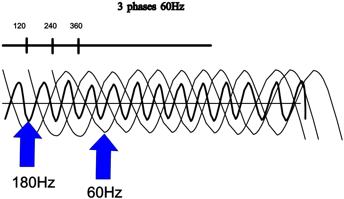
Phase AnglesAt 60 Hz, because of a 120° difference between the phases on a well-balanced three-phase system, the current is cancelled to zero on the neutral; the same technique applies for other frequencies at different angles.
For example, with two variable speed drives of equal capacity, by installing a Delta-Wye transformer (30° with respect to the primary) on one motor and a Delta-Delta transformer (0°) on the other, the common primary of the two transformers will obtain a good cancellation of the 5th and 7th harmonics.
With this approach, we can use all of the non-linear loads and by phase shifting the loads, attenuate the effects of certain harmonics.
Meanwhile, because of the relation between the current and voltage distortions, the impedance takes on important dimensions. Therefore, new transformers have been designed to offer low impedance to triplet-type harmonics and others have been designed to offer low impedance cancellation for other harmonic types.
Meanwhile, because of the relation between the current and voltage distortions, the impedance takes on important dimensions. Therefore, new transformers have been designed to offer low impedance to triplet-type harmonics and others have been designed to offer low impedance cancellation for other harmonic types.
-
 G12V190PZL1 JDEC JICHAI JINAN дизельный двигатель марки CHIDONG запчасти воздушный фильтр 12VB.36M.40/50
-
Высокочастотный трансформатор для сварки термопластов и производства автомобильных внутренних деталей
-
Трансформатор тока шинного типа KCT-816 с раздвижным сердечником
-
Трансформатор тока разъемного сердечника шинной шины с выходом 5А для устройств контроля
-
KCT-816 2500:5A Шина-типа раздельно-кольцевые трансформаторы тока
-
RS1000-1500A/333mV Открыто-закрытый трехфазный гибкий rogowski-кованный токовый трансформатор
-
Гибкий токовый трансформатор на основе Rogowski-ой катушки для измерения высокочастотных переменных токовых сигналов
-
Дешевый
-
Трансформатор электроизоляционного типа
-
Цены завода-производителя. Цены на трехфазный понижающий трансформатор
-
Высокопроизводительный трехфазный промышленный сухой реактор с железным сердечником на переменный ток
-
Производитель
-
Популярные рекомендации. Трехфазный трансформатор. Сухой трансформатор
-
Профессиональная фабрика. Трехфазный трансформатор. Сухой трансформатор
-
Китайский завод. Эпоксидно-массовый сухой трансформатор высокого напряжения для распределительной сети
-
Трехфазный сухой трансформатор
-
Эпоксидная смола
-
Реактор высокого напряжения
Популярные поиски
- Электрический трансформатор
- Сервис распределения
- трансформатор тока
- Электрические трансформаторы
- Высокочастотный трансформатор
- Электрический трансформатор
- устройство для экономии энергии
- LED-трансформаторы
- повышающий преобразователь
- Преобразователь переменного тока
- Преобразователь частоты
- электронный трансформатор
- Светотрансформаторы
- Тороидальный трансформатор
- автотрансформатор
- трансформатор тока, индуктивность
