
- Hainan Jinpan Smart Technology Co., Ltd.
- Основные продукты: Трансформатор с заливом смолой, Трансформатор с вакуумной пропиткой изоляции, Выключатель для открытых подстанций, Средненапряжные комплектные блок-подстанции
Главная > Новости компании > Electrical Problems on Non-linear Electrical Systems

-
 Song
Добро пожаловать в мой магазин. Я рад вам обслуживать. Не стесняйтесь задавать мне любые вопросы.
Song
Добро пожаловать в мой магазин. Я рад вам обслуживать. Не стесняйтесь задавать мне любые вопросы.
Ваше сообщение превысило лимит.
Новости компании
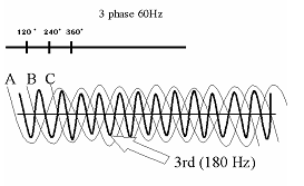
A switching power supply takes a portion of the maximum positive energy as well as the minimum negative energy on the sine wave. This deforms the sine wave, provoking a new wave.
Fourier, the French mathematician, demonstrated that this new wave can be broken down as the sum of many waves (harmonics), for which the fundamental is at 60 Hz, and of all the present harmonics, the 2nd at 120 Hz, the 3rd at 180 Hz, etc.
A spectral analysis gives us the amplitude of these waves and allows us to compare the relative importance of each of these.
| Harmonics spectral analysis IEE Standard - 519-1992 | |||
| Harmonic | Amplitude | Harmonic | Amplitude |
| 1 | 1.000 | 9 | 0.157 |
| 3 | 0.810 | 11 | 0.024 |
| 5 | 0.606 | 13 | 0.063 |
| 7 | 0.370 | 15 | 0.079 |
The RMS value of a deformed current is given by:
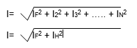
I = RMS value of the deformed current
IF = RMS value of the fundamental
IH = RMS value of the harmonics
I2, I3, I4, ... IN = Respective RMS values of the 2nd, 3rd, 4th, ... Nth harmonics
A similar equation is applied for voltage.
Example:
With a current for which the RMS value is 100 A at the fundamental (60 Hz) and 80 A at the 3rd harmonic (180 Hz), the RMS value of the deformed current is therefore:
![]()
Harmonics and cause fuses and circuit breakers to open a circuit for no apparent reason. An installation capable of supporting a certain amount of linear loads could no longer be able to support it after being replaced with non-linear loads of the same power at 60 Hz. We should be seeing a rapid progression of this type of problem as new non-linear harmonic loads are added or replace traditional linear loads.
With energy saving programs, utilities lead their customers to use switching power supply technology such as variable speed drives and electronic ballasts.
The laws of electricity have not changed but our knowledge of them becomes essential:
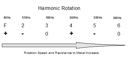
The more the frequency increases, the more the metal becomes resistant (skin effect).
Certain harmonics are at direct sequences (1, 4, 7, 10), others inverse (2, 5, 8, 11), and others without sequence, are called triplets (3, 6, 9).
Harmonics can damage transformers.
Inverse harmonics have harmful effect on motors.
Harmonics influence the power factor.
In a factory, if we find a certain amount of current harmonics, is there a problem?
Ohm's law (V=IR) with a few exceptions, explains the consequences of these harmonics on inductive and resistive loads. Current distortions will create voltage distortions according to the line impedance. It is well known that for any non-linear load installation, it is very important that the impedance be as low as possible. One should always foresee the consequences of a current distortion on voltage or on the harmonic voltage distortion that it can bring about. Current harmonics are always present in non-linear loads and if they are properly dealt with, they will not always be problem sources.
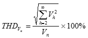
IEEE Standard 519-1992
Harmonic voltage distortion limits
in % of nominal fundamental frequency voltage.
| Bus Voltage at PCC (Vn) | Individual Harmonic Voltage Distortion (%) | Total Voltage Distortion - THDVn (%) |
| 3.0 | 5.0 | |
| 1.5 | 2.5 | |
| 1.0 | 1.5 |
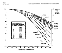
As mentioned earlier, the more the frequency increases the more the metal becomes resistant. Therefore, the current has the tendency to stick to the outer surfaces of the conductor (skin effect). The electric conductor, which was designed for 60 Hz, will heat up when powered up with higher frequencies. Therefore, the conductor must be reclassified. Here is a recommendation from the IEEE Standard 519-2014 on this subject:
Cable declassifications factor in terms of the percentage of harmonics for a 6 impulse three-phase converter used for VSDs.
On a 60 Hz, delta-wye, 4 wire transformer, if the loads on the phases are well balanced, the current (I) on the neutral side is cancelled at the 60 Hz frequency because of the vectorial sum of each of the phases (120º between each of them).
As per the IEEE Standard 519-1992 on a three-phase system for which the loads are solely computers, for a current of 100 amps at 60 Hz, we find a current of 81 amps at 180 Hz. Given that with 120º between each phase, at the frequency of 180 Hz, there is no cancellation on the neutral; it possesses a current that is the sum of each phase current at 180 Hz. The RMS value of the current on the neutral is therefore greater than the phase current (see Electrical Problems on Non-linear Electrical Systems).
The neutral will heat up if it is not of an adequate size for a non-linear load. Also, because of the wire's impedance, a voltage will appear on the load between the neutral and the ground. This voltage can be very damaging for electronic equipment (ex.: signal brought to ground).
The transformer overheats because of the increased losses due to the Eddie currents, caused by the presence of harmonics in the winding conductors.
MotorsMotors operate with a positive rotation at a frequency of 60 Hz. So, if the frequency is a negative sequence (ex.: 5th voltage harmonic), the resultant force will provoke heating, as well as a decrease in the total motor torque because this type of frequency brings about an inverse rotational effect on the motor. This phenomenon will bring about an additional stress, which will provoke premature failure of the motors. An unbalanced voltage will bring about a negative rotation sequence.
Variable Speed Drives
Variable speed drives have become very popular in industrial electric installations beginning with DC motors and later with AC motors. Both types use the alternating current and transform it to DC to control the motor’s speed. However, because of this process, they create current harmonics on the line and are very sensitive to voltage fluctuations.
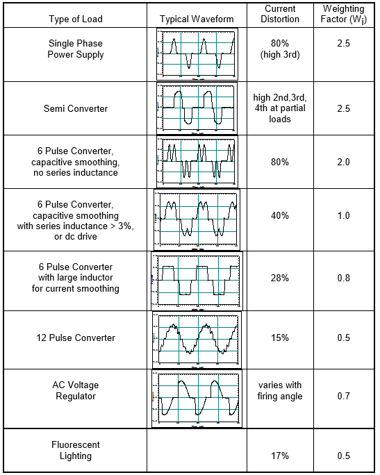
IEEE Standard 519-1992
Weighting factors for different types of harmonic producing loads.
Protection of Electrical Systems
There is a great deal of electrical protection systems on the market. The choices we make will depend on the needs and complexity of their application, as well as their cost.
Circuit Breakers and FusesWhen choosing circuit breakers and fuses, the true RMS (Root Mean Square) current values must be taken into consideration. To do this, measurements must always be taken with true RMS value equipment, meaning a current reading including harmonic values (see Electrical Problems on Non-linear Electrical Systems).
-
 G12V190PZL1 JDEC JICHAI JINAN дизельный двигатель марки CHIDONG запчасти воздушный фильтр 12VB.36M.40/50
-
Высокочастотный трансформатор для сварки термопластов и производства автомобильных внутренних деталей
-
Трансформатор тока шинного типа KCT-816 с раздвижным сердечником
-
Трансформатор тока разъемного сердечника шинной шины с выходом 5А для устройств контроля
-
KCT-816 2500:5A Шина-типа раздельно-кольцевые трансформаторы тока
-
RS1000-1500A/333mV Открыто-закрытый трехфазный гибкий rogowski-кованный токовый трансформатор
-
Гибкий токовый трансформатор на основе Rogowski-ой катушки для измерения высокочастотных переменных токовых сигналов
-
Дешевый
-
Трансформатор электроизоляционного типа
-
Цены завода-производителя. Цены на трехфазный понижающий трансформатор
-
Высокопроизводительный трехфазный промышленный сухой реактор с железным сердечником на переменный ток
-
Производитель
-
Популярные рекомендации. Трехфазный трансформатор. Сухой трансформатор
-
Профессиональная фабрика. Трехфазный трансформатор. Сухой трансформатор
-
Китайский завод. Эпоксидно-массовый сухой трансформатор высокого напряжения для распределительной сети
-
Трехфазный сухой трансформатор
-
Эпоксидная смола
-
Реактор высокого напряжения
Популярные поиски
- Электрический трансформатор
- Сервис распределения
- трансформатор тока
- Электрические трансформаторы
- Высокочастотный трансформатор
- Электрический трансформатор
- устройство для экономии энергии
- LED-трансформаторы
- повышающий преобразователь
- Преобразователь переменного тока
- Преобразователь частоты
- электронный трансформатор
- Светотрансформаторы
- Тороидальный трансформатор
- автотрансформатор
- трансформатор тока, индуктивность
